Table of Contents
02 Layout & Design
Block Diagram
-
Background color of block diagram is grey (RGB = 226/226/226; 'Indicator Background') where applicable
VI & Control Icons
You can find tips and tricks around LabVIEW's icon editor in the LabVIEW section of the dokuwiki.
-
NO DEFAULT ICONS
-
Do not use VIs or Controls with the LabVIEW default icon
-

-
Icons that make sense
-
Manage common icon templates in project repository
-
Have a background layer (→ alignment of text)
-

-
When working inside a library or class, use its icon template
-
Leave the layer NI_Library intact
-
you can edit it for all members in the General Settings of the class/library properties dialog
-
you can import it from the owning library in the Icon Editor
When working with accessors in a class (those available as property nodes), changing the VI's documentation or icon is unnecessary as neither show up in code.Connector Pattern
-
Stick to the Default Connector Pattern (4 × 2 × 2 × 4)
-
For selected helper VIs, it is allowed to deviate from the default connector pattern
-
Example: Logger VIs

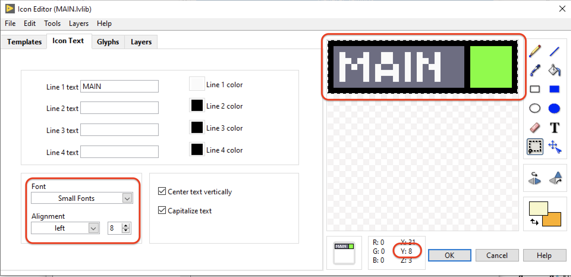
Icon Layout
-
Icons have a coloured rectangle on top
-
The colour is derived from the category of the module, see below
-
8px banner height
-
8 or 9pt font size
The coloured rectangle can contain textTo differentiate modules of the same category, augment the coloured rectangle with…-
another arbitrarily coloured square on the right side
-
a glyph on the right side (can be higher than the rectangle)


Constant VIs

-
For constant VIs, color the bottom right corner of the VI icon in black
Icon Colors
HSE libs and modules
 RGB = 108/0/128
hampelsoft-libraries, and other modules and templates from Hampel Software Engineering
Main, State, Sequence
 RGB = 109/109/131 ('Slide Housing')
Main program for a programmable hardware, sequencer, state machines
UI
 RGB = 100/255/0 ('LED on')
User Interface, Results Display, Visualization, Log & Debug Views
Error
 RGB = 255/0/0 ('Thermometer Fill')
Error handlers inside modules, shutdown VIs, emergency stop
Hardware
 RGB = 0/65/220 ('Slide Fill')
Generic control of a specific, “non-programmable” hardware like a camera, motor, DC source (NOT: cRIO, FPGA, PLC, …)
Storing/Logging
 RGB = 255/255/204
Writing data to file/database, save images
Communication
 RGB = 255/153/255
Other Software, Internet, PLC, Database, RS-232, etc.
Data Acq./Processing
 RGB = 255/128/0
Data Acquisition, Data processing, feature extraction, feature evaluation, calculations…
_Examples and _VI Templates
 RGB = 251/223/255
For _Example VIs and _VI Templates.
Special Case: Converters
If converting from or to specific LabVIEW data types, try and use the corresponding wire color in the icon.
Example: Convert from integer to single: Left side is blue, right side is orange.

Icon Glyphs
Glyphs are stored in LabVIEW's data folder, eg.
C:\Users\admin\Documents\LabVIEW Data\Glyphs\Broadcast VIs

-
Marks VIs that broadcast data into the world
-
[DQMH] Separates Broadcast VIs visually from other request VIs
-
Obsolete for DQMH since release 4.2!
The HSE Way of Working:
A set of guidelines that recommend programming style, better practices, and methods for all our LabVIEW projects. We ask all our peers to follow these guidelines to help improve the readability of our shared source code and make software maintenance easier.kb/bestpractices/codingconventions/layout-design.txt · Last modified: 2025/01/29 08:28 by joerg.hampel
-
-
-
-
-
-


